B engine water pump rebuild using standard industry parts
Posted: Wed Dec 30, 2009 12:22 am
I’m not a big fan of people converting B engine cars to electric water pumps if the water pump shafts are still in good condition. Since the pump needs to be removed regardless I’d rather see the pump rebuilt then go with an electric pump that won’t last as long as a standard pump. Some people convert to electric because they can’t find the rebuild kits. To solve this dilemma I sourced all of the parts in a standard rebuild kit from McMaster-Carr (an industrial supplier) for about $35.
Below is a parts list including part numbers and a water pump rebuilding tutorial.
All parts sourced from http://www.mcmaster.com
Bearing:
McMaster part #: 3760T4 http://www.mcmaster.com/#3760t4/=556dxe
Price: $17.93
Industry standard: R10, open
Manufaturer: NSK (built to ABEC-3 rating)
Circlip/snap ring:
McMaster part #: 97633A230 http://www.mcmaster.com/#97633a230/=556gcf
Price: $0.10 (sold in bags of 100, if anyone wants some let me know and I can mail them)
Size: 5/8” snap ring
Oil Seal:
McMaster part #: 5154T34 http://www.mcmaster.com/#5154t34/=556kzk
Price: $6.84
Industry standard: Spring loaded shaft seal, double lip for 5/8" shaft, 1 3/8" bore
Manufacturer: SKF (part # 6373)
Water seal:
McMaster part #: 9281k183 http://www.mcmaster.com/#9281k183/=556hy4
Price: $6.71
Type: 304 Industry standard: #1000
Manufacturer: Pac-Seal Flowserve
Gasket material:
McMaster part #: 75125A66 http://www.mcmaster.com/#75125a66/=556ly0
Price: $15.36 (enough to do more than one complete engine) You’ll use about $0.50 worth
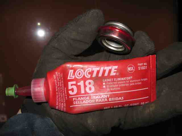
Loctite 518 flange sealant and gasket eliminator
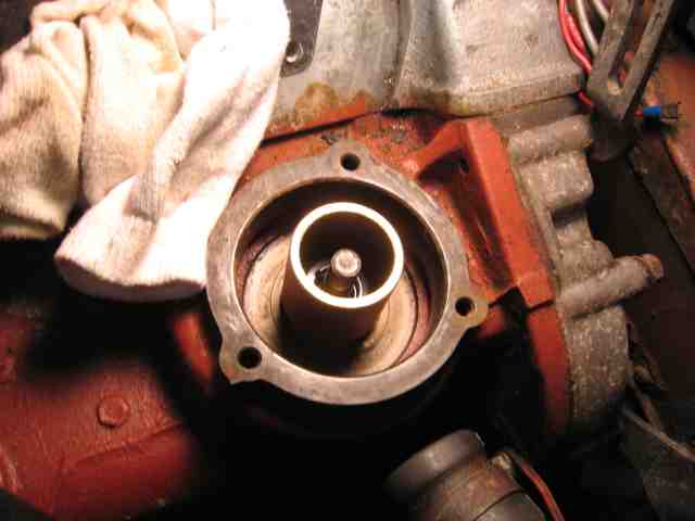
The first step is to drain the coolant, remove the alternator, slide the alternator bracket out of the way, remove the hoses from the water pump cover and intake manifold, remove the intake manifold and remove the water pump cover.
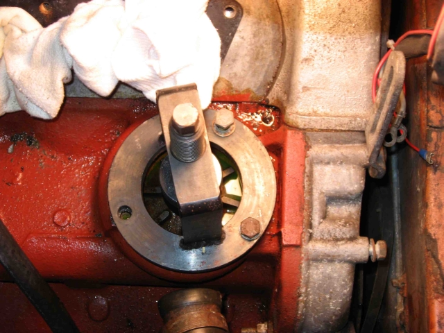
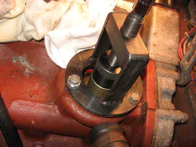
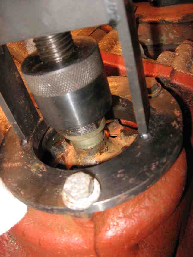
Then fit the water pump tool by threading it onto the water pump shaft. The threads are a left hand thread and I think there may have been different thread sizes. Some impellers have a bolt and some have a nut and some have nothing but interference holding them on. If you have to remove a bolt or nut, do it carefully and try to hold the impeller steady so that the pump doesn’t spin as you remove the fastener (you don’t want to damage the gear teeth on the shafts). Use the pump tool to pull the pump out. It will spin as it comes up because of the pitch on the gear teeth.
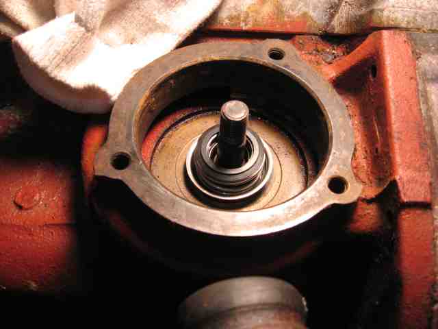
Pulling out the pump:
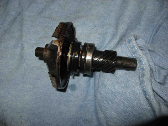
Pump removed:
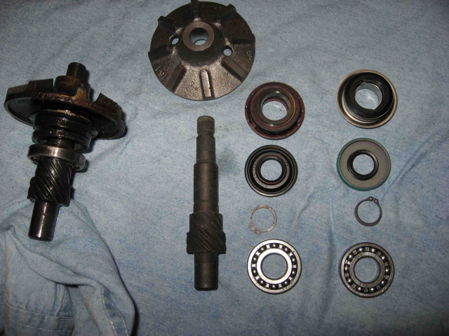
Old pump on left, OEM rebuild kit in center, new parts for rebuild from McMaster on right:
Now press the impeller off the shaft. Support the impeller from the underside and place a flat tool on top of the shaft when pressing. I use an Allen socket, 8mm when pressing an externally threaded pump shaft. It contacts flat on top of the shaft and is chamfered so it doesn’t interfere with the threads.
Remove the water and oil seals and remove the circlip. Press off the bearing.
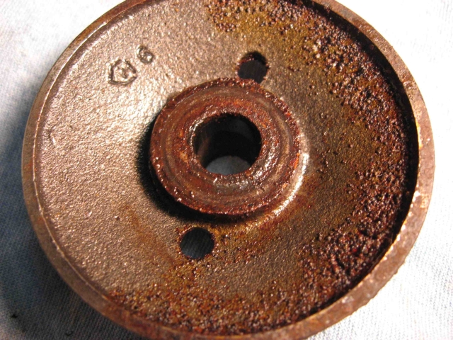
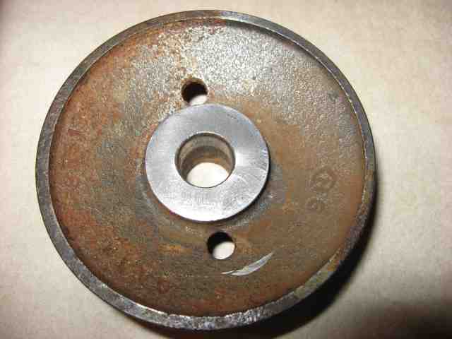
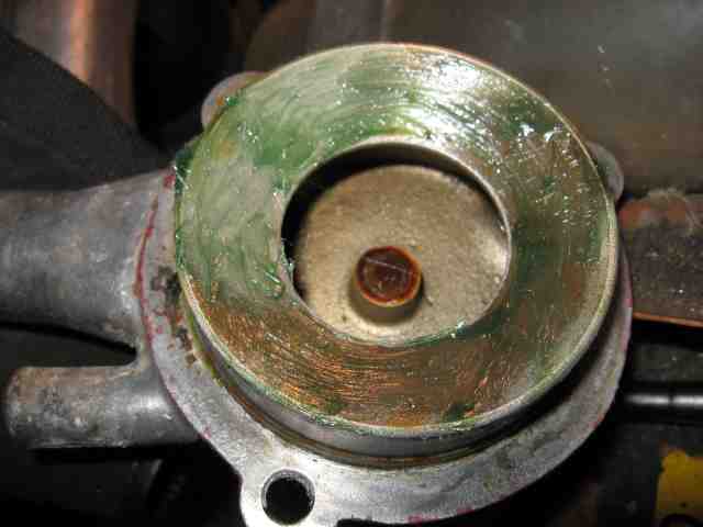
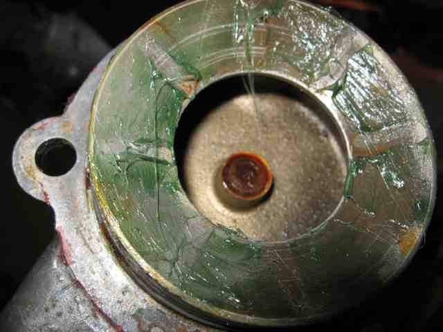
Inspect the impeller. Typically they might be corroded and a grove is worn in them where the water seal contacted. You’ll want to touch up this surface before re-assembling so that the water seal won't leak.
The underside of this impeller was pretty nasty, the engine had been sitting for a while:
I had a friend of mine who is a machinist touch up the seal contact area:
Clean the shaft, the recess in the block where the water pump was removing the old gasket, cleaning the water seal contact surface, the bearing contact surface, and the recess that the bottom of the pump shafts sits in (using Q-tips).
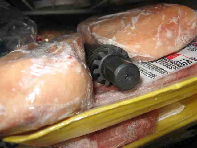
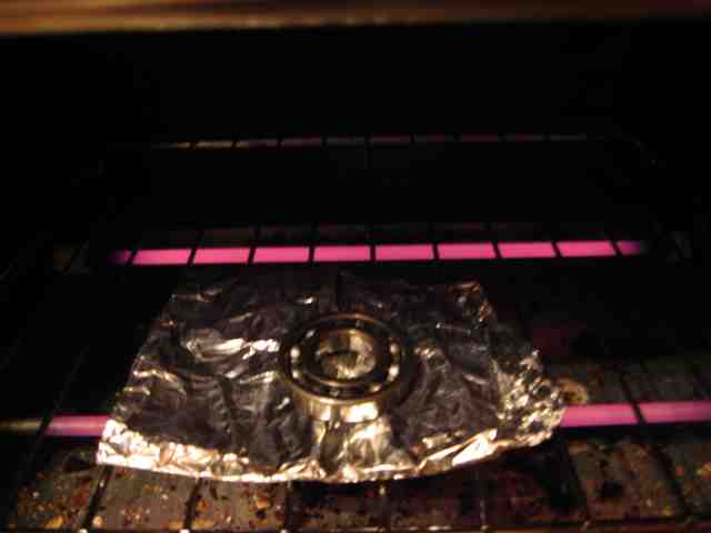
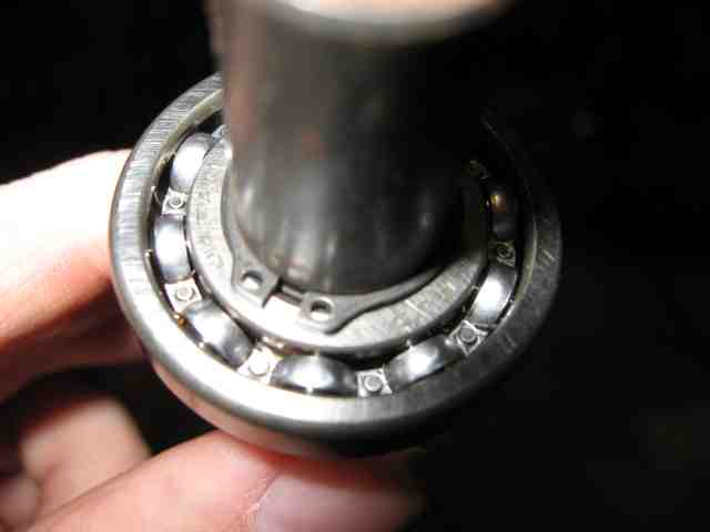
To make assembling the bearing onto the pump shaft a little easier you can chill the pump shaft in the freezer and heat the bearing to around 200F.
Cold shaft:
Toasty bearing:
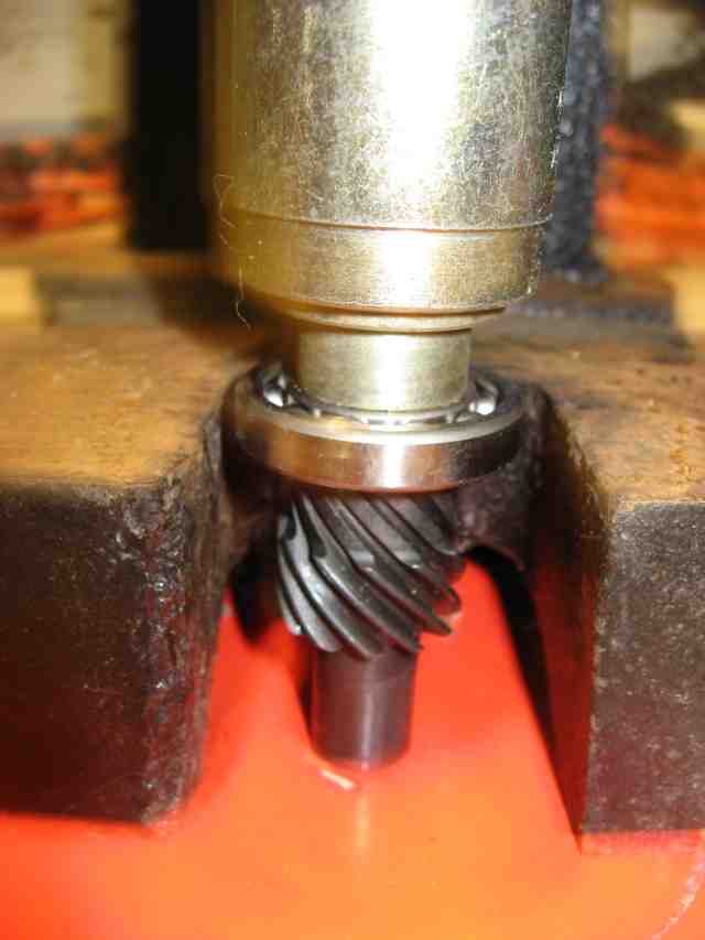
Work quickly when slipping the bearing on as the temperatures will equalize quickly. Press the bearing onto the shaft until it stops by only pressing on the inner race.
Pressing on the bearing:
Put on the circlip:
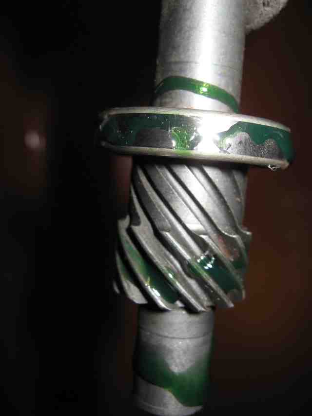
Oil the bearing and gear teeth with assembly oil:
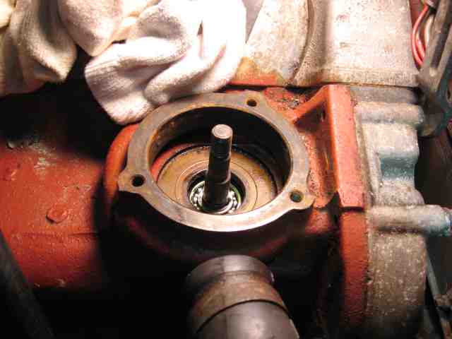
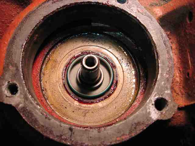
Set the pump into the block:
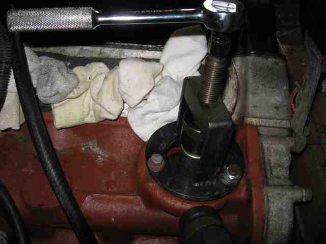
Press the pump down in by only pressing on the outer race of the bearing.
Slip the oil seal on in the orientation shown.
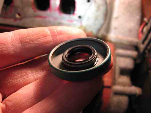
Use the same adapter on the pump tool that was used the press the pump in. Press the oil seal on but do not press hard once the seal stops moving. You don’t want to put too much force down because the metal side of the seal will contact the circlip and you don’t want it to dig in too much.
Put a little Loctite 518 flange sealant under the flange of the water seal.
Set the water seal in place and press it in only contacting the outer flange of the seal.
Set the impeller on the pump shaft. Smear a thin layer of grease on the underside of the water pump cover.
Test fit the pump cover. You’ll notice that the cover won’t fit all the way down and the impeller leaves impressions in the grease.
Fit the pump tool and slowly push the impeller on. Go in small steps removing the tool and test fitting the pump cover to check for interference. It will be necessary to remove and refit the pump tool a number of times but it will be worth it in the end. You want the pump cover to be as close to the impeller as possible in order to maximize pump efficiency (99’s need all the help they can get cooling the engine).
As soon as there is no more contact between the pump cover and impeller, clean the grease off the cover and impeller, put some Loctite 518 on the block in place of the cover gasket and fit the pump cover.
Replace the manifold (you can use Loctite 518 in place of the gasket), hoses, and alternator. Let the Loctite 518 cure for a few hours (it is an anaerobic compound and will start curing as soon as it is clamped and there is no oxygen in it’s vicinity). Change the engine oil and re-fill the cooling system.
This one dribbled a little coolant out of the weep hole once it got up to full operating temperature. The dribbling stopped after 5 or 10 minutes. This is typical as the water seal beds into the impeller. These seals are intended to ride against a smooth ceramic surface. A ceramic disk actually comes with the part from McMaster.
Earlier water pumps are enclosed in a brass cage. The only real difference is that all of the parts are inside the cage and there are two o-rings on the outside of the cage. I don’t have one of those water pumps available, otherwise I would have measured the O-rings and included them in the parts list.
Below is a parts list including part numbers and a water pump rebuilding tutorial.
All parts sourced from http://www.mcmaster.com
Bearing:
McMaster part #: 3760T4 http://www.mcmaster.com/#3760t4/=556dxe
Price: $17.93
Industry standard: R10, open
Manufaturer: NSK (built to ABEC-3 rating)
Circlip/snap ring:
McMaster part #: 97633A230 http://www.mcmaster.com/#97633a230/=556gcf
Price: $0.10 (sold in bags of 100, if anyone wants some let me know and I can mail them)
Size: 5/8” snap ring
Oil Seal:
McMaster part #: 5154T34 http://www.mcmaster.com/#5154t34/=556kzk
Price: $6.84
Industry standard: Spring loaded shaft seal, double lip for 5/8" shaft, 1 3/8" bore
Manufacturer: SKF (part # 6373)
Water seal:
McMaster part #: 9281k183 http://www.mcmaster.com/#9281k183/=556hy4
Price: $6.71
Type: 304 Industry standard: #1000
Manufacturer: Pac-Seal Flowserve
Gasket material:
McMaster part #: 75125A66 http://www.mcmaster.com/#75125a66/=556ly0
Price: $15.36 (enough to do more than one complete engine) You’ll use about $0.50 worth
Loctite 518 flange sealant and gasket eliminator
The first step is to drain the coolant, remove the alternator, slide the alternator bracket out of the way, remove the hoses from the water pump cover and intake manifold, remove the intake manifold and remove the water pump cover.
Then fit the water pump tool by threading it onto the water pump shaft. The threads are a left hand thread and I think there may have been different thread sizes. Some impellers have a bolt and some have a nut and some have nothing but interference holding them on. If you have to remove a bolt or nut, do it carefully and try to hold the impeller steady so that the pump doesn’t spin as you remove the fastener (you don’t want to damage the gear teeth on the shafts). Use the pump tool to pull the pump out. It will spin as it comes up because of the pitch on the gear teeth.
Pulling out the pump:
Pump removed:
Old pump on left, OEM rebuild kit in center, new parts for rebuild from McMaster on right:
Now press the impeller off the shaft. Support the impeller from the underside and place a flat tool on top of the shaft when pressing. I use an Allen socket, 8mm when pressing an externally threaded pump shaft. It contacts flat on top of the shaft and is chamfered so it doesn’t interfere with the threads.
Remove the water and oil seals and remove the circlip. Press off the bearing.
Inspect the impeller. Typically they might be corroded and a grove is worn in them where the water seal contacted. You’ll want to touch up this surface before re-assembling so that the water seal won't leak.
The underside of this impeller was pretty nasty, the engine had been sitting for a while:
I had a friend of mine who is a machinist touch up the seal contact area:
Clean the shaft, the recess in the block where the water pump was removing the old gasket, cleaning the water seal contact surface, the bearing contact surface, and the recess that the bottom of the pump shafts sits in (using Q-tips).
To make assembling the bearing onto the pump shaft a little easier you can chill the pump shaft in the freezer and heat the bearing to around 200F.
Cold shaft:
Toasty bearing:
Work quickly when slipping the bearing on as the temperatures will equalize quickly. Press the bearing onto the shaft until it stops by only pressing on the inner race.
Pressing on the bearing:
Put on the circlip:
Oil the bearing and gear teeth with assembly oil:
Set the pump into the block:
Press the pump down in by only pressing on the outer race of the bearing.
Slip the oil seal on in the orientation shown.
Use the same adapter on the pump tool that was used the press the pump in. Press the oil seal on but do not press hard once the seal stops moving. You don’t want to put too much force down because the metal side of the seal will contact the circlip and you don’t want it to dig in too much.
Put a little Loctite 518 flange sealant under the flange of the water seal.
Set the water seal in place and press it in only contacting the outer flange of the seal.
Set the impeller on the pump shaft. Smear a thin layer of grease on the underside of the water pump cover.
Test fit the pump cover. You’ll notice that the cover won’t fit all the way down and the impeller leaves impressions in the grease.
Fit the pump tool and slowly push the impeller on. Go in small steps removing the tool and test fitting the pump cover to check for interference. It will be necessary to remove and refit the pump tool a number of times but it will be worth it in the end. You want the pump cover to be as close to the impeller as possible in order to maximize pump efficiency (99’s need all the help they can get cooling the engine).
As soon as there is no more contact between the pump cover and impeller, clean the grease off the cover and impeller, put some Loctite 518 on the block in place of the cover gasket and fit the pump cover.
Replace the manifold (you can use Loctite 518 in place of the gasket), hoses, and alternator. Let the Loctite 518 cure for a few hours (it is an anaerobic compound and will start curing as soon as it is clamped and there is no oxygen in it’s vicinity). Change the engine oil and re-fill the cooling system.
This one dribbled a little coolant out of the weep hole once it got up to full operating temperature. The dribbling stopped after 5 or 10 minutes. This is typical as the water seal beds into the impeller. These seals are intended to ride against a smooth ceramic surface. A ceramic disk actually comes with the part from McMaster.
Earlier water pumps are enclosed in a brass cage. The only real difference is that all of the parts are inside the cage and there are two o-rings on the outside of the cage. I don’t have one of those water pumps available, otherwise I would have measured the O-rings and included them in the parts list.